Wednesday, 14 March 2012

Week 8: Build Load Appliances

Week No: 8
Date: 14/3/2012


Title of Activity: Build Load Appliances


Objective:


1) To realizing what have been plan before.
2) To integrate with other circuit to make this project work.
3) To make people see how this project can control motor or electrical machine
4) To make the star-delta and forward reverse motor starter circuit before connected to motor.
5) To protect motor from large starting current.
6) To control motor speed, power and direction.


Content / Procedure:


1) List down all the component that will be used in the circuit.
2) Draw the circuit of star-delta and forward reverse on the paper for reference.
3) Do the wiring according to the circuit.
4) Test the circuit.


Result and analysis:


1) The circuit consist of:
 - Ac contector 
 - Cable 2.5 mm
 - Overload relay (2x)
 - Timer
 - Miniature circuit breaker (2x)
All these component will be used in the circuit


2) Ac contector function is to control the circuit, this as contactor have a normally open and normally close like relay and can be use with timer to make the circuit to operate according to what we plan.


3) Cable 2.5mm is the usual size of cable that being used, but if the horse power of the motor is bigger or the current that will be passing through is large, we have to used a bigger size cable. The size of the cable can be refer to the table in IEE rules and regulation book.


4) Overload relay function is to control the current in the circuit, if the overload current happens in the circuit or current flow is bigger than the value that we set, it will trip and stop the motor.
5) Timer function is to delay some action in the circuit, and usually it will be use with the ac contector.


6) Miniature circuit breaker function is to trip when this is a over current in the circuit, over current happen when short circuit happens and this device is to protect the user from shock.


Conclusion:


1) The motor that i will be use in this project is squirrel cage induction motor and the motor starter circuit that i will use is suitable with the motor based on cable size and miniature circuit breaker size.


2) For now i will make the motor starter circuit only and connect with the motor when all thing is done.


3) This motor starter circuit will be connected with load driving circuit to make it work.


Picture of Stat-Delta and Forward Reverse starter circuit:


Figure 1: Main star-delta circuitry 

Figure 2: Control star-delta circuitry


Figure 3: Main and control Forward Reverse circuitry


Thursday, 8 March 2012

Week 7: Motion Sensing Development Circuit

Week No: 7
Date: 8/3/2012


Title of Activity: Motion sensing development circuit


Objective:


1) To realizing what have been plan before.
2) To integrate with other circuit to make this project work.
3) To sensing movement at certain places
4) To detect intruder


Content / Procedure:


1) Buy the motion PIR sensor from store.
2) Read the user manual and understand it.
3) Try to incorporate it with the main circuit.


Result and analysis: 


1) PIR sensor means Passive Infra-red sensor.


2) This motion PIR sensor is a pyroelectric device that  can detect infrared rays released by human body motion within the detection area of 5 meters.


3) The PIR sensor can sense even in night mode.


4) If there is an intruder who wish to enter the factory, the microcontroller will be activated high ‘1’ and send notification to the worker stating that intruder in factory.


5) The advantage of PIR sensor is single bit output, small size makes it easy to conceal, compatible with all types of microcontrollers, 5 v till 20 v operation.


6) Calibration - The PIR Sensor requires a ‘warm-up’ time in order to function properly. This is due to the


settling time involved in ‘learning’ its environment. This could be anywhere from 10-60
seconds.


7) Sensitivity - The PIR Sensor has a range of approximately 5 meters. The PIR sensor can sense object up to 120° within 1 meter range.


Conclusion: 


1) This PIR sensor is suitable to be used in my project because it is simple to use, easy to found and cheap.


Picture of PIR motion sensor: 


Figure 1: Product Dimension 

Figure 2: Product Layout

Figure 3: Product Actual Look


Thursday, 1 March 2012

Week 6: Current Sensing Development Circuit

Week No: 6
Date: 1/3/2012


Title of Activity: Current Sensing Development Circuit


Objective: 


1) To realizing what have been plan before.
2) To integrate with other circuit to make this project work.
3) To sensing the current in the main circuit and send the data to micro-controller.
4) To protect the main circuit from over-voltage.
5) To boost current.
6) To convert voltage from AC to DC.
7) To eliminate noise.


Content / Procedure:


1) List down all the component used in the circuit.
2) Draw the circuit in PCB lab and print out the circuit.
3) Hatching the circuit according to the setting in the PCB layout.
4) Solder the component on the circuit board.

5) Test the circuit.


Result and Analysis:


1) The circuit consist of:
 - Power resistor
 - Isolation transformer
 - Capacitor and resistor for filter
 - Operational amplifier IC
 - Diode 
All these component will be attached to the board.


2) Power resistor function is to make the value of voltage equal to current because the value of the resistor is 1 ohm.


3) Isolation transformer function is to avoid the 240 volt direct to the circuit that can cause circuit to burn.


4) Capacitor and resistor for filter function is to reduce noise in the circuit.


5) Operational amplifier IC function is to make the amplifier circuit to boost current.


6) Diode function is to convert voltage from AC to DC.


Conclusion:


1) The filter need to be design more specific and functional to reduce noise more efficiently.
2) Power resistor need to be cover up because it can shock people if accidentally touch.


Picture of Current Sensing Circuit:


Figure 1: Top view

Figure 2: Bottom view


Thursday, 23 February 2012

Week 5: Load Driving Development Circuit

Week No: 5
Date: 23/2/2012


Title of Activity: Load driving development circuit


Objective: 


1) To realizing what have been plan before
2) To integrate with other circuit to make this project work
3) To drive the load on and off when we need it to


Content / Procedure:


1) List down all the component used in the circuit.
2) Draw the circuit in PCB lab and print out the circuit.
3) Hatching the circuit according to the setting in the PCB layout.
4) Solder the component on the circuit board.
5) Test the circuit.


Result and Analysis:


1) The circuit board consist of:
 - RWH relay (x4)
 - Wire connector (x4)
All these component will be attached to the board.


2) RWH relay function is to switching the load or the connector that will be used to control the motor or machine. The switching capacity of the RWH relay is 10 A, spite of miniature size to comply with user's wide selection.


3) Wire connector is to connect between board and load.


Conclusion:


1) The load driving circuit need to be design more specific and functional, to make it run smoothly.


2) This circuit need to be functional because it control the load operation. 


Picture of Load Driving Circuit:


Figure 1: Top view

Figure 2: Bottom viwe


Figure 3: Complete view 


Thursday, 16 February 2012

Week 4: PCB Layout Design and Micro-controller Development Circuit

Week No: 4
Date: 16/2/2012


Title of Activity: PCB layout design and micro-controller development circuit


Objective: 


1) To estimate the main circuit board look like.
2) To make the design as small as possible.
3) To integrate all the component in the board.


Content / Procedure:


1) List down all the control component. 
2) Draw the circuit in PCB lab and print out the circuit.
3) Hatching the circuit regarding on that had setting in the PCB lab layout.
4) Solder the component on the circuit board.
5) Test the circuit.


Result and Analysis:


1) The main circuit board consist of :
     -  programmable integrated circuit (PIC)
     - MAX 232 integrated circuit (2x)
     - ULN 2003 integrated circuit
     - RS 232 port (2x)
     All of these element will be attached to the board


2) MAX 232 is the voltage level converter. It converts voltage level from CMOS (microsontroller output is CMOS) to TTL (PC output is TTL) and vice versa. But it drives voltage level from one to another voltage that is why it is also called voltage driver IC.


3) RS 232 was adopted as a standard for serial binary data signals connecting between a DTE (Data  Terminal Equipment) and DCE (Data Circuit-terminating Equipment). It is commonly used in computer serial ports. 


4) ULN 2003 is to drive the inductor type of load.


Conclusion:


1) The main circuit board need to be design more specific and functional, so that it can run smoothly.
2) MAX232 and RS232 need to be functional because it will communicate with the computer.
3) ULN2003 need to work properly because it will has to increase the voltage.


                                                       Figure 1: schematic design


Figure 2: PCB layout


                                                       Figure 3: Component placement 


Figure 4: Complete circuit 

Thursday, 9 February 2012

Week 3: Plan all the circuitry development

Week no: 3
Date: 9/2/2012


Title of Activities: Plan all the circuitry development


Objective: 


1) To make sure the circuit that i want to use in the project can work properly with other circuit.
2)  For easy to troubleshoot if there is any problem


Content / Procedure:


1) Search on the internet about the circuit that will be used in the project
2) Look for the circuit in the book or note that been given by lecturer 
3) Ask project supervisor about the circuit that will be use in the project
4) After found all the circuit that will be used in the project, consult with project supervisor about effectiveness and suitability of the circuit.


Result: 


1) Current sensing circuit
2) Relay circuit 
3) Motor control circuit


                                                       Figure 1: Current sensing circuit


                                                                   Figure 2: Relay circuit


                                                     Figure 3: Forward reverse circuit for AC motor


Conclusion: 


1) After consulting with my project supervisor Dr. Mohd Khairil Rahmat, he approve all the circuit that i have choose for this project.


2) All of this circuit is reasonable to do in the given time.

Thursday, 2 February 2012

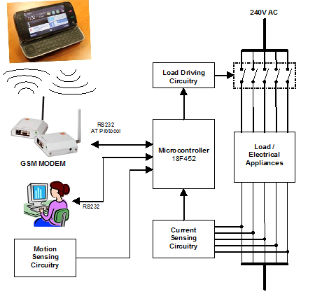
Week 2: Block Diagram and Flow Chart

Week no: 2
Date: 2/2/2012


Title of Activities: Block Diagram and Flow Chart 


Objective:


1) To make this project is easy to understand and look reliable.
2) To test write the program in the proper way.


Content / Procedure:


1) Making the block diagram from input processor & output.
2) To make a flow in the proper way to write the program.
3) Understanding how the project operate by referring to the flowchart & block diagram.


Result and Analysis :


1) By using a block diagram to understand this project more easier.
2) The flowchart is made to start the program writing. 3) Understanding how the project operate by referring to the flowchart & block diagram.
2) Thus, the flowchart is really important in this project. So that, the progress will be going smoothly without any disturbances.


Conclusion :


1) By using block diagram & flowchart, it can give more understanding about the flow of the program to finish up this project well.


2) Thus, the flowchart is really important in this project. So that, the progress will be going smoothly without any disturbances.


Flow of the Project: 


Block Diagram of the Project: