Date: 1/3/2012
Title of Activity: Current Sensing Development Circuit
Objective:
1) To realizing what have been plan before.
2) To integrate with other circuit to make this project work.
3) To sensing the current in the main circuit and send the data to micro-controller.
4) To protect the main circuit from over-voltage.
5) To boost current.
6) To convert voltage from AC to DC.
7) To eliminate noise.
Content / Procedure:
1) List down all the component used in the circuit.
2) Draw the circuit in PCB lab and print out the circuit.
3) Hatching the circuit according to the setting in the PCB layout.
4) Solder the component on the circuit board.
5) Test the circuit.
Result and Analysis:
1) The circuit consist of:
- Power resistor
- Isolation transformer
- Capacitor and resistor for filter
- Operational amplifier IC
- Diode
All these component will be attached to the board.
2) Power resistor function is to make the value of voltage equal to current because the value of the resistor is 1 ohm.
3) Isolation transformer function is to avoid the 240 volt direct to the circuit that can cause circuit to burn.
4) Capacitor and resistor for filter function is to reduce noise in the circuit.
5) Operational amplifier IC function is to make the amplifier circuit to boost current.
6) Diode function is to convert voltage from AC to DC.
Conclusion:
1) The filter need to be design more specific and functional to reduce noise more efficiently.
2) Power resistor need to be cover up because it can shock people if accidentally touch.
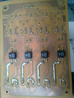
Picture of Current Sensing Circuit:
Figure 1: Top view
Figure 2: Bottom view


No comments:
Post a Comment